Raphael Fortuna ECE 3400 Wiki
Project maintained by raf269 Hosted on GitHub Pages — Theme by mattgraham
Lab 2
Home
Lab 1
Lab 3
Lab 4
Summary of what was accomplished during the lab
- We built a circuit to pulse the IR LED using a signal generator and measured the signal generator within an oscilloscope
- We built an IR frequency detection circuit with the phototransistor, connected it to the oscilloscope to measure the IR emitter frequency, and tested the circuit with the nano
- We built two other phototransistor circuits on the robot and tested them to make sure they worked
- We rewired our robot
- We created a pinout diagram for the 7-segment display and then create the 7-segment circuit
- We tested the 7-segment display with the nano
Building the IR LED and phototransistor circuit
We first determined the resistance needed to use the light emitter and then assembled the circuit on the breadboard and connected it to the signal generator and oscilloscope to make sure that it was running.
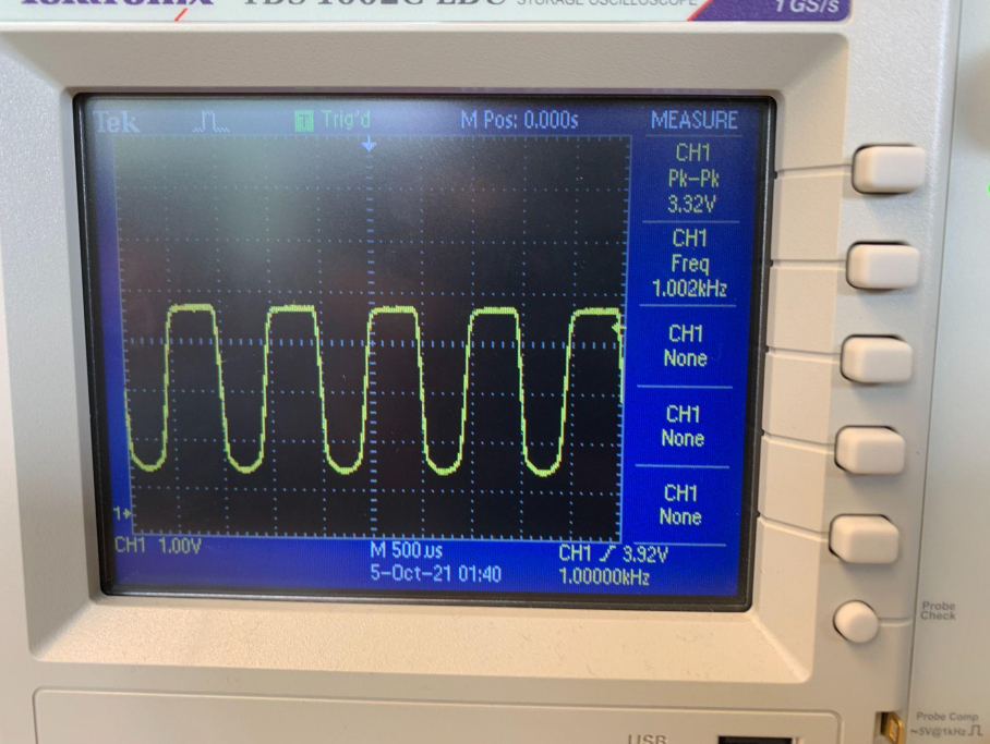
Then we built the phototransistor circuit and pointed the IR LED at the photo transistor and measured the frequency using the oscilloscope.
Here is a picture from the oscilloscope:
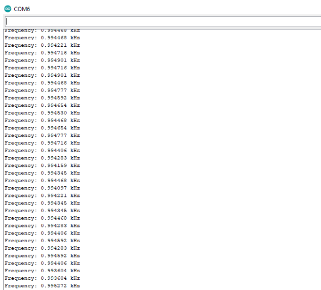
After that we added the phototransistor circuit to the robot and then tested to see if we could get the frequency using the provided code.
Here is a picture of our photoresistor circuit (also rewired):
We repeat this process with the other two photoresistor circuits on the robot.
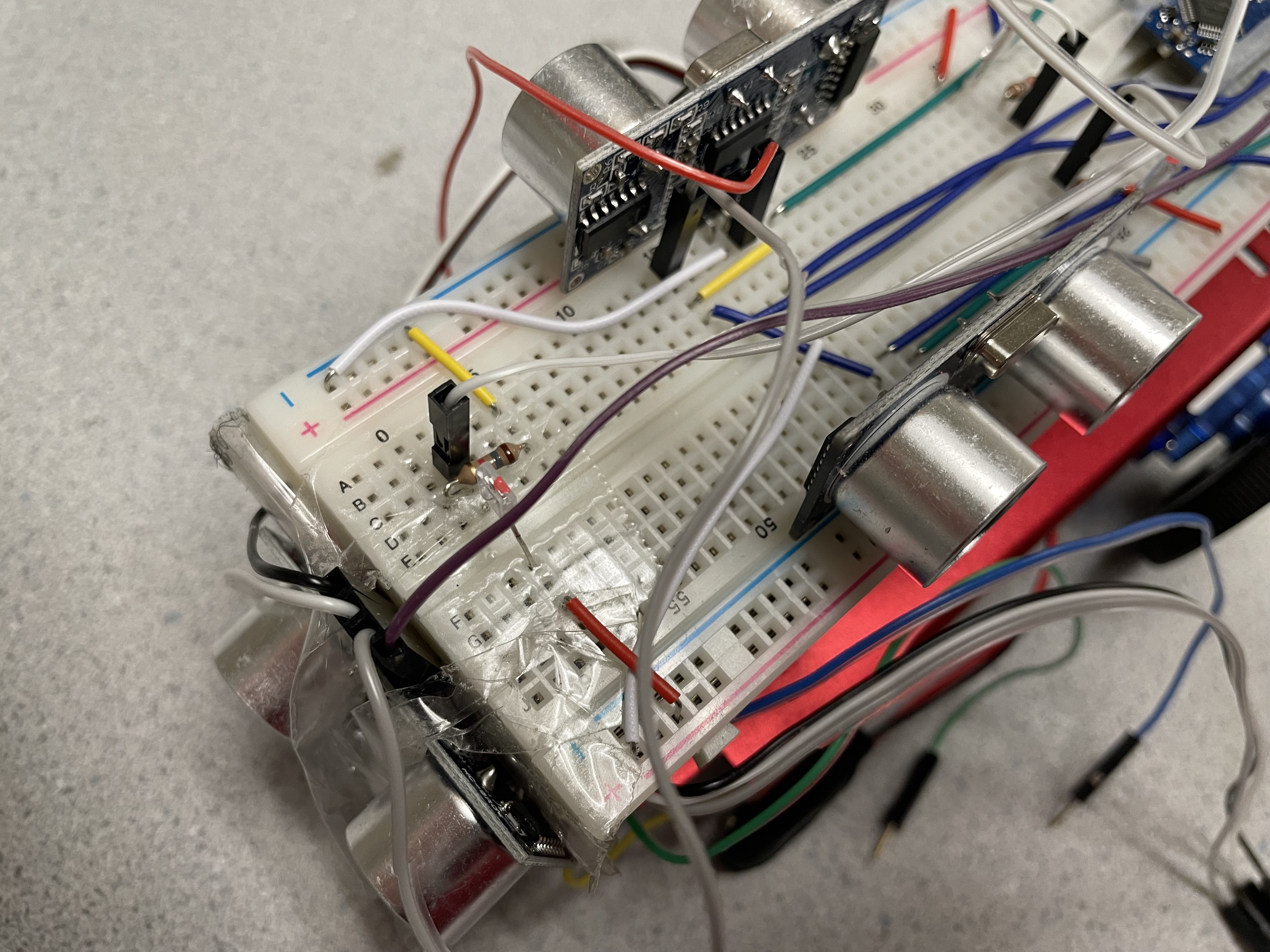
Here is a picture of our finished robot (also rewired):
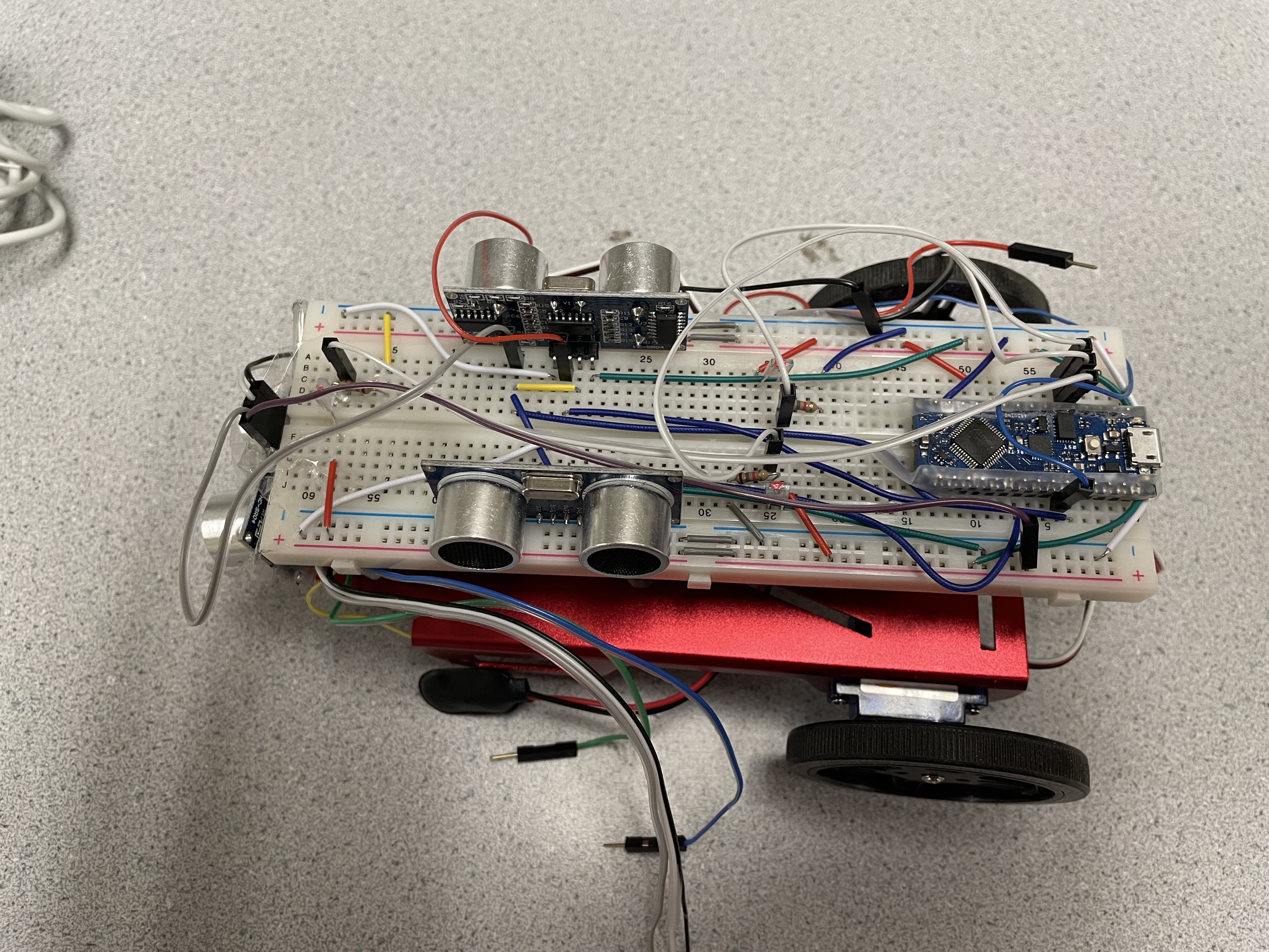
Rewiring the robot
We decided to rewire our robot since we had lots of wires sticking everywhere and we wanted to make it cleaner and easier to use as well as reduce the chance of it breaking if we were to snag on something.
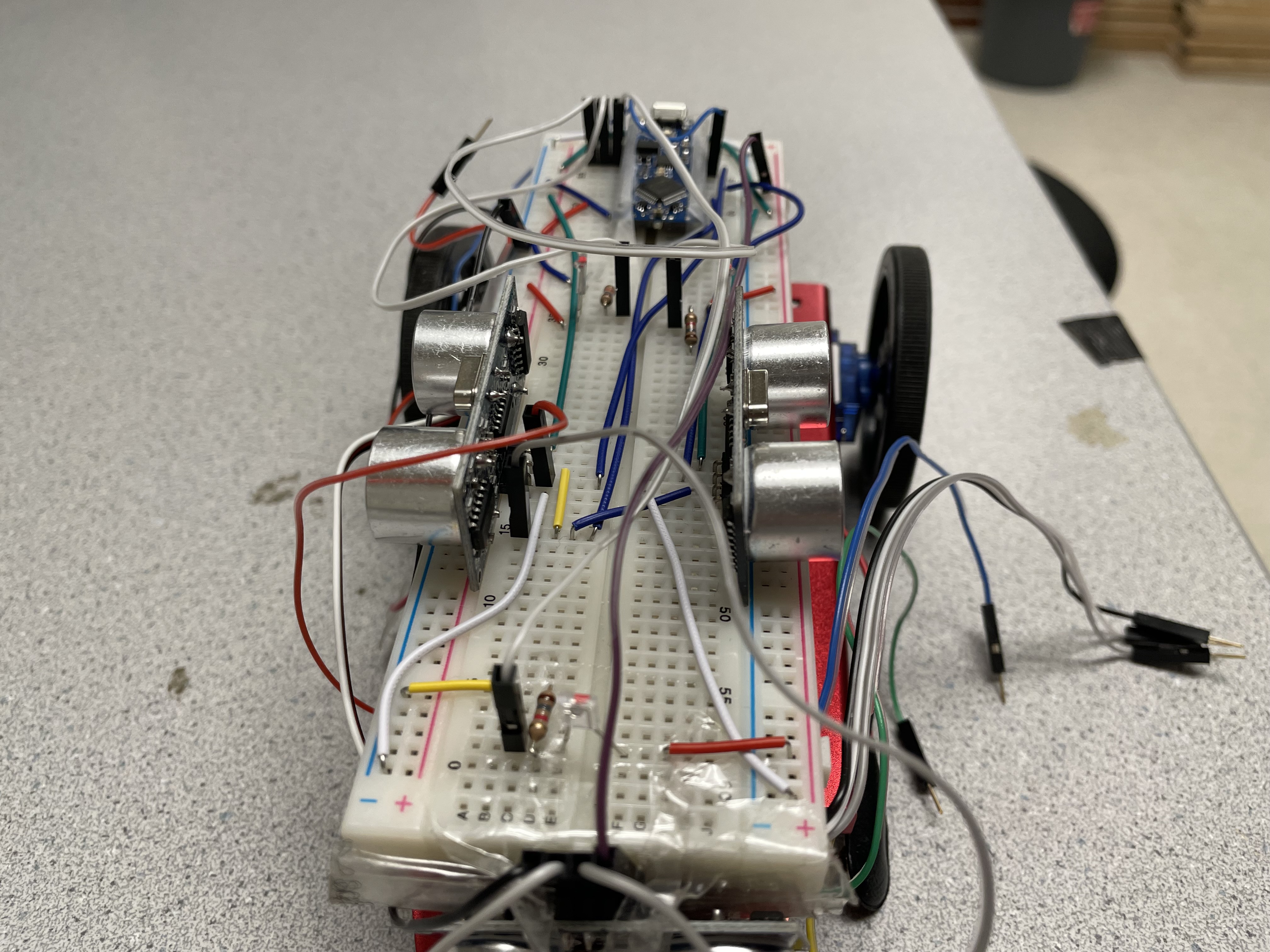
We used flat wires that were the length we needed for each circuit and utilized both sides of the breadboard power and ground lines.
We will be further testing the robot with the new circuitry during lab 3 to make sure it all still works.
Here is a picture of our rewired robot:
7-segment display circuit
To start the 7-segment display, we first created a pinout diagram for the 7-segment display since it was hard to tell where each pin went.
After that, we wired up the connections from the 7-segment display to the shift register and add wires to the shift register and the rest of the pins on the 7-segment display to the Arduino Nano.
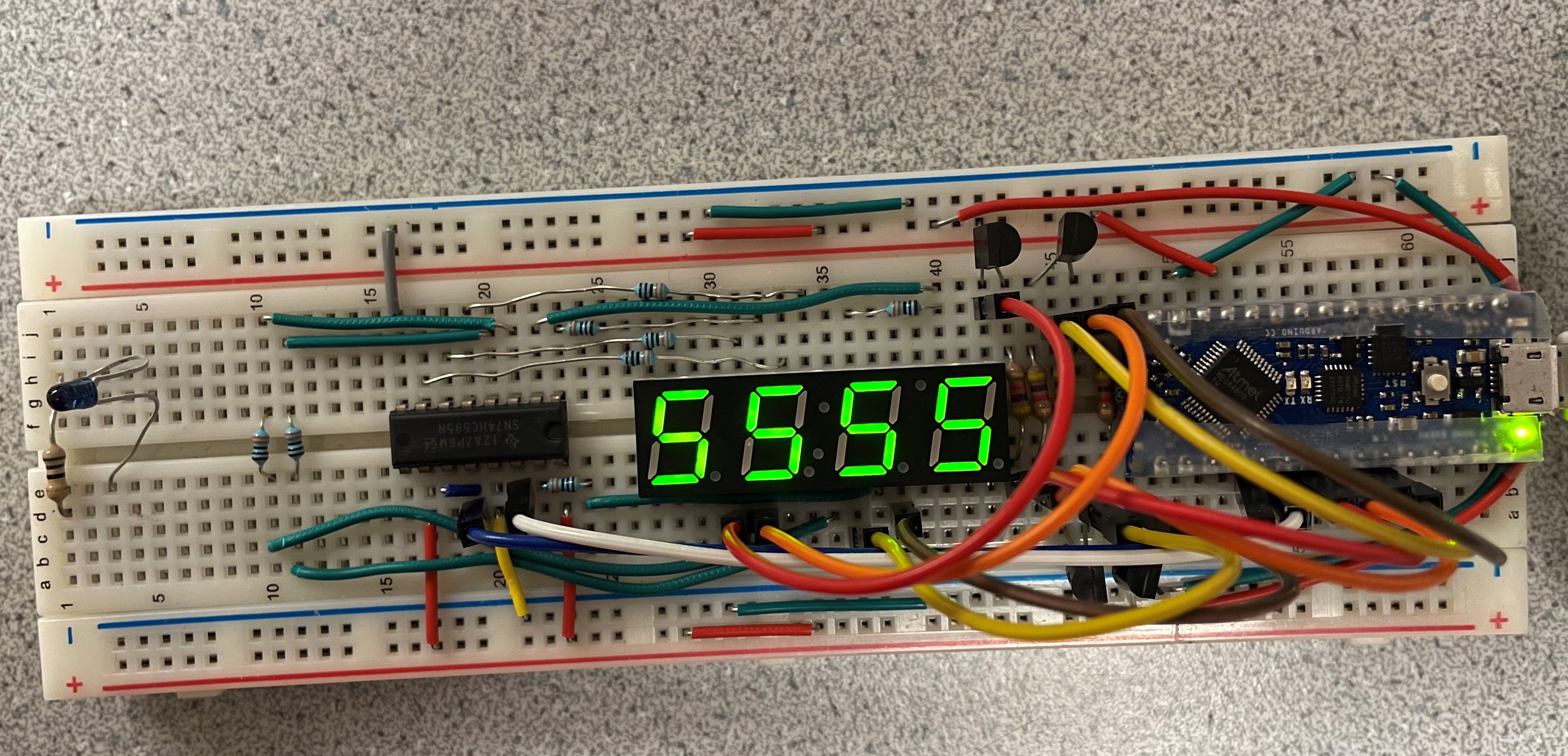
We then tested the circuit to make sure it worked using the provided code and then modified the code to be able to support decimals and show numbers greater than 9999.
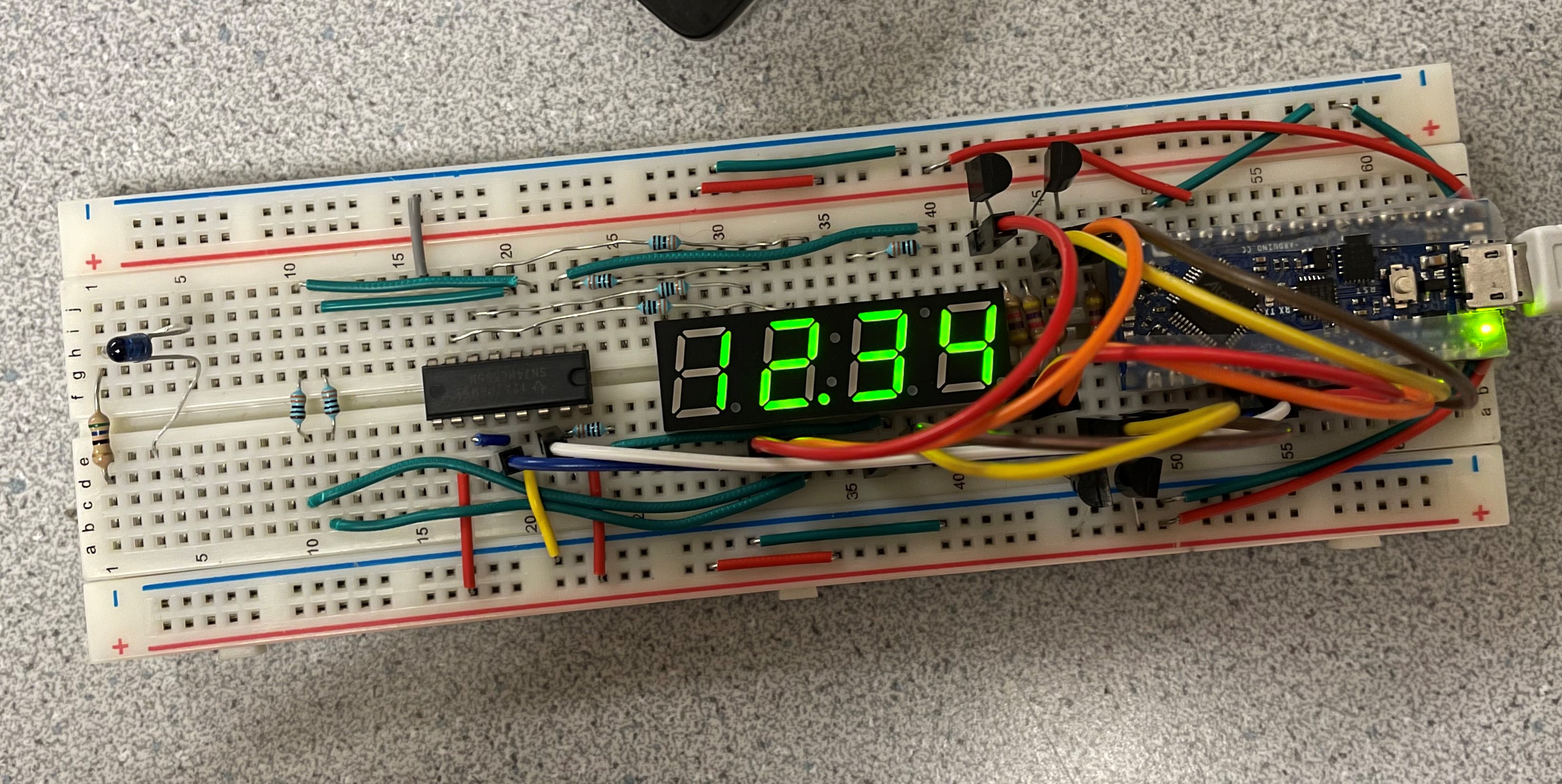
Here's a picture of the 7-segment display below:
Here's a picture of the 7-segment display below with a number greater than 9999, 12345, converted to thousands and a decimal: